==========================================
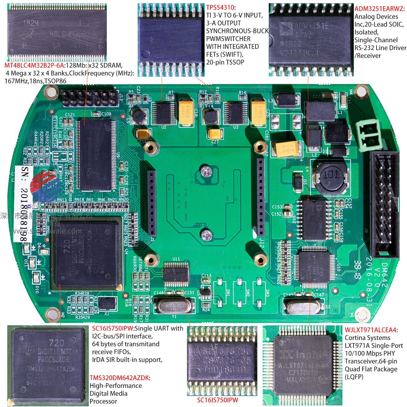
TMS320DM642AZDK(2003年版本,但不是2003年制造,一共有2003年和2005年两个版本): TI Video/Imaging Fixed-Point Digital Signal Processor
关键词:基于TMS320DM642A机器人测距系统,基于DM642A DSP,双目立体视觉,测距搜索,改进的Sobel核函数,置信度滤波器,左右一致性过滤器,DSP/BIOS操作系统,工业相机数字信号处理器DSP,德州仪器DSP,TI DSP,高精度数字媒体处理器
keywods:Based on TMS320DM642A robot ranging system, based on DM642A DSP, Binocular stereo vision, ranging search, range?finding,improved Sobel kernel function, confidence filter, left-right consistency filter, DSP/BIOS operating system, Industrial camera digital signal processor DSP, Texas Instruments DSP, TI DSP, high precision digital media processor,CAVLC;decoder ,H.264
■ High-Performance Digital Media Processor
–2-,1.67-,1.39-ns Instruction Cycle Time
–500-,600-,720-MHz Clock Rate
–Eight 32-Bit Instructions/Cycle
–4000,4800,5760 MIPS
–Fully Software-Compatible With C64x(TM)
■ VelociTI.2(TM) Extensions to VelociTI(TM) Advanced Very-Long-Instruction-Word (VLIW) TMS320C64x(TM)DSP Core
–Eight Highly Independent Functional Units With VelociTI.2(TM) Extensions:
● Six ALUs (32-/40-Bit),Each Supports Single 32-Bit, Dual16-Bit,or Quad 8-Bit Arithmetic per Clock Cycle
● Two Multipliers Support Four 16x16-Bit Multiplies (32-Bit Results) per Clock Cycle or Eight 8x8-Bit Multiplies (16-BitResults) per Clock Cycle
–Load-Store Architecture With Non-Aligned Support
–64 32-Bit General-Purpose Registers
–Instruction Packing Reduces Code Size
–All Instructions Conditional
■ Instruction Set Features
–Byte-Addressable (8-/16-/32-/64-Bit Data)
–8-Bit Overflow Protection
–Bit-Field Extract, Set,Clear
–Normalization,Saturation, Bit-Counting
–VelociTI.2(TM) Increased Orthogonality
■ L1/L2 Memory Architecture
–128K-Bit (16K-Byte) L1P Program Cache (Direct Mapped)
–128K-Bit (16K-Byte) L1D Data Cache (2-Way Set-Associative)
–2M-Bit (256K-Byte) L2 Unified Mapped RAM/Cache (Flexible RAM/Cache Allocation)
■ Endianess: Little Endian, Big Endian
■ 64-Bit External Memory Interface (EMIF)
–Glueless Interface to Asynchronous Memories (SRAM and EPROM) and Synchronous Memories (SDRAM,SBSRAM,ZBT SRAM,and FIFO)
– 1024M-Byte Total Addressable External Memory Space
■ Enhanced Direct-Memory-Access (EDMA) Controller (64 Independent Channels)
■ 10/100 Mb/s Ethernet MAC (EMAC)
– IEEE 802.3 Compliant
– Media Independent Interface (MII)
– 8 Independent Transmit (TX) Channels and 1 Receive (RX) Channel
■ Management Data Input/Output (MDIO)
■ Three Configurable Video Ports
– Providing a Glueless I/F to Common Video Decoder and Encoder Devices
– Supports Multiple Resolutions/Video Stds
■ VCXO Interpolated Control Port (VIC)
– Supports Audio/Video Synchronization
■ VCXO Interpolated Control Port (VIC)
– Supports Audio/Video Synchronization
■ Host-Port Interface (HPI) [32-/16-Bit]
■ 32-Bit/66-MHz, 3.3-V Peripheral Component Interconnect (PCI) Master/Slave Interface Conforms to PCI Specification 2.2
■ Multichannel Audio Serial Port(MCASP)
– Eight Serial Data Pins
– Wide Variety of I2s and Similar Bit Stream Formats Integrated Digital Audio I/F Transmitter Supports S/PDIF, IEC60958-1, AES-3, CP-430 Formats
■ Inter-Integrated Circuit (IC Bus TM)
■ Two Multichannel Buffered Serial Ports
■ Three 32-Bit General-Purpose Timers
■ Sixteen General-Purpose I/O (GPIO) Pins
■ Flexible PLL Clock Generator
■ IEEE-1149.1 (JTAG) Boundary-Scan-Compatible
■ 548-Pin Ball Grid Array (BGA) Package (GDK and ZDK Suffixes), 0.8-mm Ball Pitch
■ 548-Pin Ball Grid Array (BGA) Package (GNZ and ZNZ Suffixes), 1.0-mm Ball Pitch
■ 0.13-μm/6-Level Cu Metal Process(CMOS)
■ 3.3-V I/O, 1.2-V Internal(-500)
■ 3.3-V I/O, 1.4-V Internal (A-500, A-600, -600, -720)
The TMS320C64x(TM) DSPs (including the TMS320DM642 device) are the highest-performance fixed-point DSP generation in the TMS320C6000(TM) DSP platform.
The TMS320DM642 (DM642) device is based on the second-generation high-performance, advanced VelociTI(TM) very-long-instruction-word (VLIW) architecture (VelociTI.2(TM)) developed by Texas Instruments (TI), making these DSPs an excellent choice for digital media applications. The C64x(TM) is a code-compatible member of the C6000(TM) DSP platform.
With performance of up to 5760 million instructions per second (MIPS) at a clock rate of 720 MHz, the DM642 device offers cost-effective solutions to high-performance DSP programming challenges. The DM642 DSP possesses the operational flexibility of high-speed controllers and the numerical capability of array processors. The C64x(TM) DSP core processor has 64 general-purpose registers of 32-bit word length and eight highly independent functional units—two multipliers for a 32-bit result and six arithmetic logic units (ALUs)—with VelociTI.2(TM) extensions. The VelociTI.2? extensions in the eight functional units include new instructions to accelerate the performance in video and imaging applications and extend the parallelism of the VelociTI(TM) architecture. The DM642 can produce four 16-bit multiply-accumulates (MACs) per cycle for a total of 2880 million MACs per second (MMACS), or eight 8-bit MACs per cycle for a total of 5760 MMACS. The DM642 DSP also has application-specific hardware logic, on-chip memory, and additional on-chip peripherals similar to the other C6000(TM) DSP platform devices.
The DM642 uses a two-level cache-based architecture and has a powerful and diverse set of peripherals. The Level 1 program cache (L1P) is a 128-Kbit direct mapped cache and the Level 1 data cache (L1D) is a 128-Kbit 2-way set-associative cache. The Level 2 memory/cache (L2) consists of an 2-Mbit memory space that is shared between program and data space. L2 memory can be configured as mapped memory, cache, or combinations of the two. The peripheral set includes: three configurable video ports; a 10/100 Mb/s Ethernet MAC (EMAC); a management data input/output (MDIO) module; a VCXO interpolated control port (VIC); one multichannel buffered audio serial port (McASP0); an inter-integrated circuit (I2C) Bus module; two multichannel buffered serial ports (McBSPs); three 32-bit general-purpose timers; a user-configurable 16-bit or 32-bit host-port interface (HPI16/HPI32); a peripheral component interconnect (PCI); a 16-pin general-purpose input/output port (GP0) with programmable interrupt/event generation modes; and a 64-bit glueless external memory interface (EMIFA), which is capable of interfacing to synchronous and asynchronous memories and peripherals.
The DM642 device has three configurable video port peripherals (VP0, VP1, and VP2). These video port peripherals provide a glueless interface to common video decoder and encoder devices. The DM642 video port peripherals support multiple resolutions and video standards (e.g., CCIR601, ITU-BT.656, BT.1120, SMPTE 125M, 260M, 274M, and 296M).
These three video port peripherals are configurable and can support either video capture and/or video display modes. Each video port consists of two channels --A and B with a 5120-byte capture/display buffer that is splittable between the two channels.
For more details on the Video Port peripherals, see the TMS320C64x DSP Video Port/VCXO Interpolated Control (VIC) Port Reference Guide (literature number SPRU629).
The McASP0 port supports one transmit and one receive clock zone, with eight serial data pins which can be individually allocated to any of the two zones. The serial port supports time-division multiplexing on each pin from 2 to 32 time slots. The DM642 has sufficient bandwidth to support all 8 serial data pins
transmitting a 192-kHz stereo signal. Serial data in each zone may be transmitted and received on multiple serial data pins simultaneously and formatted in a multitude of variations on the Philips Inter-IC Sound (I2S) format.
In addition, the McASP0 transmitter may be programmed to output multiple S/PDIF, IEC60958, AES-3, CP-430 encoded data channels simultaneously, with a single RAM containing the full implementation of user data and channel status fields.
McASP0 also provides extensive error-checking and recovery features, such as the bad clock detection circuit for each high-frequency master clock which verifies that the master clock is within a programmed frequency range.
The VCXO interpolated control (VIC) port provides digital-to-analog conversion with resolution from 9-bits to up to 16-bits. The output of the VIC is a single bit interpolated D/A output.For more details on the VIC port, see the TMS320C64x DSP Video Port/VCXO Interpolated Control (VIC) Port Reference Guid (literature number SPRU629).
The ethernet media access controller (EMAC) provides an efficient interface between the DM642 DSP core processor and the network. The DM642 EMAC support both 10Base-T and 100Base-TX, or 10 Mbits/second (Mbps) and 100 Mbps in either half- or full-duplex, with hardware flow control and quality of
service (QOS) support. The DM642 EMAC makes use of a custom interface to the DSP core that allows efficient data transmission and reception. For more details on the EMAC, see the TMS320C6000 DSP Ethernet Media Access Controller (EMAC) / Management Data Input/Output (MDIO) Module Reference
Guide (literature number SPRU628).
The management data input/output (MDIO) module continuously polls all 32 MDIO addresses in order to enumerate all PHY devices in the system. Once a PHY candidate has been selected by the DSP, the MDIO module transparently monitors its link state by reading the PHY status register. Link change events
are stored in the MDIO module and can optionally interrupt the DSP, allowing the DSP to poll the link status of the device without continuously performing costly MDIO accesses. For more details on the MDIO, see the TMS320C6000 DSP Ethernet Media Access Controller (EMAC) / Management Data Input/Output (MDIO) Module Reference Guide (literature number SPRU628).
The I2C0 port on the TMS320DM642 allows the DSP to easily control peripheral devices and communicate with a host processor. In addition, the standard multichannel buffered serial port (McBSP) can be used to communicate with serial peripheral interface (SPI) mode peripheral devices.
The DM642 has a complete set of development tools which includes: a new C compiler, an assembly optimizer to simplify programming and scheduling, and a Windows? debugger interface for visibility into source code execution.
1.1 Device Compatibility
The DM642 device is a code-compatible member of the C6000(TM) DSP platform.
The C64x(TM) DSP generation of devices has a diverse and powerful set of peripherals. For more detailed information on the device compatibility and similarities / differences among the DM642 and other C64x(TM) devices, see the TMS320DM642 Technical Overview (literature number SPRU615).
=====================================================
WJLXT971ALCEA4:Cortina Systems LXT971A Single-Port 10/100 Mbps PHY Transceiver,64-pin Quad Flat Package (LQFP)
The Cortina Systems(TM) LXT971A/972A/972M Single-Port 10/100 Mbps PHY Transceiver (LXT971A PHY) directly supports both 100BASE-TX and 10BASE-T applications. It provides a Media Independent Interface (MII) for easy attachment to 10/100 Media Access Controllers (MACs). The LXT971A PHY is IEEE compliant, and provides a Low Voltage Positive Emitter Coupled Logic (LVPECL) interface for use with 100BASE-FX fiber networks. The LXT971A PHY supports full-duplex operation at 10 Mbps and 100 Mbps. Operating conditions for the LXT971A PHY can be set using auto-negotiation, parallel detection, or manual control. The LXT971A PHY is fabricated with an advanced CMOS process and requires only a single 2.5/3.3 V power supply. (This Datasheet also supports the LXT971 PHY.)
Applications
■ Combination 10BASE-T/100BASE-TX or 100BASE-FX Network Interface Cards (NICs)
■ Network printers
■ 10/100 Mbps PCMCIA cards
■ Cable Modems and Set-Top Boxes
Product Features
■ 3.3 V Operation
■ Low power consumption (300 mW typical)
■ Low-power “Sleep” mode
■ 10BASE-T and 100BASE-TX using a single RJ-45 connection
■ IEEE 802.3-compliant 10BASE-T or 100BASE-TX ports with integrated filters
■ Auto-negotiation and parallel detection
■ MII interface with extended register capability
■ Robust baseline wander correction
■ Carrier Sense Multiple Access / Collision Detection (CSMA/CD) or full-duplex operation
■ JTAG boundary scan
■ MDIO serial port or hardware pin configurable
■ 100BASE-FX fiber-optic capable
■ Integrated, programmable LED drivers
■ 64-ball Plastic Ball Grid Array (PBGA) or 64-pin Quad Flat Package (LQFP)
■ LXT971ABC - Commercial (0° to 70 °C amb.)
■ LXT971ABE - Extended (-40° to 85 °C amb.)
■ LXT971ALC - Commercial (0° to 70 °C amb.)
■ LXT971ALE - Extended (-40° to 85 °C amb.)
■ LXT972ALC - Commercial (0° to 70 °C amb.)
=======================================
ADM3251EARWZ:Analog Devices Inc,20-Lead SOIC,Isolated, Single-Channel RS-232 Line Driver/Receiver
官网价格$5.685,37pcs/Tube包装,-40 to 85°C
(https://www.analog.com/en/products/adm3251e.html#product-samplebuy),
FEATURES
■ 2.5 kV fully isolated (power and data) RS-232 transceiver
■ isoPower integrated, isolated dc-to-dc converter
■ 460 kbps data rate
■ 1 Tx and 1 Rx
■ Meets EIA/TIA-232E specifications
■ ESD protection on RIN and TOUT pins
±8 kV: contact discharge
±15 kV: air gap discharge
■ 0.1 μF charge pump capacitors
■ High common-mode transient immunity: >25 kV/μs
■ Safety and regulatory approvals
UL recognition
2500 V rms for 1 minute per UL 1577
VDE Certificate of Conformity
DIN EN 60747-5-2 (VDE 0884 Teil 2): 2003-01
CSA Component Acceptance Notice #5A
■ Operating temperature range: ?40°C to +85°C
■ Wide body, 20-lead SOIC package
APPLICATIONS
■ High noise data communications
■ Industrial communications
■ General-purpose RS232 data links
■ Industrial/telecommunications diagnostic ports
■ Medical equipment
GENERAL DESCRIPTION
The ADM3251E1 is a high speed, 2.5 kV fully isolated, singlechannel RS-232/V.28 transceiver device that operates from a single 5 V power supply. Due to the high ESD protection on the RIN and TOUT pins, the device is ideally suited for operation in electrically harsh environments or where RS-232 cables are
frequently being plugged and unplugged.
The ADM3251E incorporates dual-channel digital isolators with isoPower? integrated, isolated power. There is no requirement to use a separate isolated dc-to-dc converter. Chip-scale transformer iCoupler? technology from Analog Devices, Inc., is used both for the isolation of the logic signals as well as for the integrated dc-to-dc converter. The result is a total isolation solution.
The ADM3251E contains isoPower technology that uses high frequency switching elements to transfer power through the transformer. Special care must be taken during printed circuit board (PCB) layout to meet emissions standards. Refer to Application Note AN-0971, Control of Radiated Emissions with
isoPower Devices, for details on board layout considerations.
The ADM3251E conforms to the EIA/TIA-232E and ITU-T V. 28 specifications and operates at data rates up to 460 kbps.
Four external 0.1 μF charge pump capacitors are used for the voltage doubler/inverter, permitting operation from a single 5 V supply.
The ADM3251E is available in a 20-lead, wide body SOIC package and is specified over the ?40°C to +85°C temperature range.
============================================
SC16IS750:Single UART with I2C-bus/SPI interface, 64 bytes of transmitand receive FIFOs, IrDA SIR built-in support
SC16IS750IPW,TSSOP24, plastic thin shrink small outline package; 24 leads; body width 4.4 mm,Version:SOT355-1.
1. General descriptionThe SC16IS740/750/760 is a slave I2C-bus/SPI interface to a single-channel highperformance UART. It offers data rates up to 5 Mbit/s and guarantees low operating andsleeping current. The SC16IS750 and SC16IS760 also provide the application with 8additional programmable I/O pins. The device comes in very small HVQFN24, TSSOP24(SC16IS750/760) and TSSOP16 (SC16IS740) packages, which makes it ideally suitablefor handheld, battery operated applications. This family of products enables seamlessprotocol conversion from I2C-bus or SPI to and RS-232/RS-485 and are fully bidirectional.
The SC16IS760 differs from the SC16IS750 in that it supports SPI clock speeds up to15 Mbit/s instead of the 4 Mbit/s supported by the SC16IS750, and in that it supportsIrDA SIR up to 1.152 Mbit/s. In all other aspects, the SC16IS760 is functionally andelectrically the same as the SC16IS750. The SC16IS740 is functionally and electricallyidentical to the SC16IS750, with the exception of the programmable I/O pins which areonly present on the SC16IS750.
The SC16IS740/750/760's internal register set is backward-compatible with the widelyused and widely popular 16C450. This allows the software to be easily written or portedfrom another platform.
The SC16IS740/750/760 also provides additional advanced features such as autohardware and software flow control, automatic RS-485 support, and software reset. Thisallows the software to reset the UART at any moment, independent of the hardware resetsignal.
2. Features
2.1 General featuresn
■ Single full-duplex UART
■ Selectable I2C-bus or SPI interface
■ 3.3 V or 2.5 V operation
■ Industrial temperature range:?40°C to +95°C
■ 64 bytes FIFO (transmitter and receiver)
■ Fully compatible with industrial standard 16C450 and equivalent
■ Baud rates up to 5 Mbit/s in 16× clock mode
■ Auto hardware flow control usingRTS/CTS
■ Auto software flow control with programmable Xon/Xoff characters
■ Single or double Xon/Xoff characters
■ Automatic RS-485 support (automatic slave address detection)
■ Up to eight programmable I/O pins (SC16IS750 and SC16IS760 only)
■ RS-485 driver direction control viaRTS signal
■ RS-485 driver direction control inversion
■ Built-in IrDA encoder and decoder interface
■ SC16IS750 supports IrDA SIR with speeds up to 115.2 kbit/s
■ SC16IS760 supports IrDA SIR with speeds up to 1.152 Mbit/s1
■ Software reset
■ Transmitter and receiver can be enabled/disabled independent of each other
■ Receive and Transmit FIFO levels
■ Programmable special character detection
■ Fully programmable character formatting
5-bit, 6-bit, 7-bit or 8-bit character
Even, odd, or no parityu1, 11?2, or 2 stop bits
■ Line break generation and detection
■ Internal Loopback mode
■ Sleep current less than 30μA at 3.3 V
■ Industrial and commercial temperature ranges
■ Available in HVQFN24, TSSOP24 (SC16IS750/760) and TSSOP16 (SC16IS740)packages
2.2
■ I2C-bus featuresnNoise filter on SCL/SDA inputs
■ 400 kbit/s maximum speed
■ Compliant with I2C-bus fast speed
■ Slave mode only
2.3 SPI features
■ SC16IS750 supports 4 Mbit/s maximum SPI clock speed
■ SC16IS760 supports 15 Mbit/s maximum SPI clock speed
■ Slave mode only
■ SPI Mode 0
3. Applications
■ Factory automation and process control
■ Portable and battery operated devices
■ Cellular data devices
4. Ordering informatio
Table 1.Ordering information
Type number /Package Name/ Description/ Version
■ SC16IS740IPW TSSOP16 plastic thin shrink small outline package; 16 leads; body width 4.4 mmSOT403-1
■ SC16IS750IBS HVQFN24 plastic thermal enhanced very thin quad flat package; no leads;24 terminals; body 4×4×0.85 mm SOT616-3
■ SC16IS750IPW TSSOP24 plastic thin shrink small outline package; 24 leads; body width 4.4 mmSOT355-1
■ SC16IS760IBS HVQFN24 plastic thermal enhanced very thin quad flat package; no leads;24 terminals; body 4×4×0.85 mmSOT616-3
■ SC16IS760IPW TSSOP24 plastic thin shrink small outline package; 24 leads; body width 4.4 mmSOT355-1
======================================
TPS54310: TI 3-V TO 6-V INPUT, 3-A OUTPUT SYNCHRONOUS-BUCK PWMSWITCHER WITH INTEGRATED FETs (SWIFT),20-pin TSSOP ,
FEATURES
■ 60-MOhm MOSFET Switches for High Efficiency at 3-A Continuous Output Source or Sink Current
■ 0.9-V to 3.3-V Adjustable Output Voltage With 1% Accuracy
■ Externally Compensated for Design Flexibility
■ Fast Transient Response
■ Wide PWM Frequency: Fixed 350 kHz, 550 kHz, or Adjustable 280 kHz to 700 kHz
■ Load Protected by Peak Current Limit and Thermal Shutdown
■ Integrated Solution Reduces Board Area and Total Cost
APPLICATIONS
■ Low-Voltage, High-Density Systems With Power Distributed at 5 V or 3.3 V
■ Point of Load Regulation for High Performance DSPs, FPGAs, ASICs, and Microprocessors
■ Broadband, Networking and Optical Communications Infrastructure
■ Portable Computing/Notebook PCs
DESCRIPTION
As members of the SWIFT family of dc/dc regulators, the TPS54310 low-input-voltage high-output-current synchronous-buck PWM converter integrates all required active components. Included on the substrate with the listed features are a true, high performance, voltage error amplifier that provides high performance under transient conditions; an undervoltage-lockout circuit to prevent start-up until the input voltage reaches 3 V; an internally and externally set slow-start circuit to limit in-rush currents; and a power good output useful for processor/logic reset, fault signaling, and supply sequencing.
The TPS54310 device is available in a thermally enhanced 20-pin TSSOP (PWP) PowerPAD package, which eliminates bulky heatsinks. TI provides evaluation modules and the SWIFT designer software tool to aid in quickly achieving high-performance power supply designs to meet aggressive equipment development cycles.
=======================================================
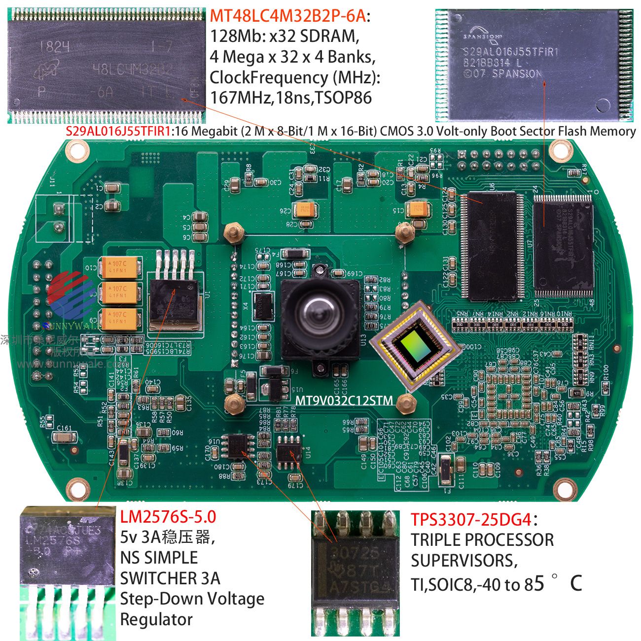
S29AL016J55TFIR1:16 Megabit (2 M x 8-Bit/1 M x 16-Bit) CMOS 3.0 Volt-only Boot Sector Flash Memory
16=16 Megabit Flash Memory manufactured using 110 nm process technolog,
55=55ns Access Spee,
T=Thin Small Outline Package (TSOP), Standard Pinou,
F=Pb-Fre,
I= Industrial (-40°C to +85°C,
R1=VCC=3.0-3.6V, top boot sector device (CFI Suppor;
(Datasheet page13)
Distinctive Characteristics
Architectural Advantages
■ Single Power Supply Operation
- Full voltage range: 2.7 to 3.6 volt read and write operations for battery-powered applications
■ Manufactured on 110 nm Process Technology
- Fully compatible with 200 nm S29AL016D
■ Secured Silicon Sector region
- 128-word/256-byte sector for permanent, secure identification
■ through an 8-word/16-byte random Electronic Serial Number accessible through a command sequence
- May be programmed and locked at the factory or by the customer
■ Flexible Sector Architecture
- One 16 Kbyte, two 8 Kbyte, one 32 Kbyte, and thirty-one 64 Kbyte sectors (byte mode)
- One 8 Kword, two 4 Kword, one 16 Kword, and thirty-one 32 Kword sectors (word mode)
■ Sector Group Protection Features
- A hardware method of locking a sector to prevent any program or erase operations within that sector
- Sectors can be locked in-system or via programming equipment
- Temporary Sector Unprotect feature allows code changes in
previously locked sectors
■ Unlock Bypass Program Command
- Reduces overall programming time when issuing multiple program command sequences
■ Top or Bottom Boot Block Configurations Available
■ Compatibility with JEDEC standards
- Pinout and software compatible with single-power supply Flash
- Superior inadvertent write protection
Performance Characteristics
■ High Performance
- Access times as fast as 55 ns
- Extended temperature range (–40°C to +125°C)
■ Ultra Low Power Consumption (typical values at 5 MHz)
- 0.2 μA Automatic Sleep mode current
- 0.2 μA standby mode current
- 7 mA read current
- 20 mA program/erase current
■ Cycling Endurance: 1,000,000 cycles per sector typical
■ Data Retention: 20 years typical
Package Options
■ 48-ball Fine-pitch BGA
■ 64-ball Fortified BGA
■ 48-pin TSOP
Software Features
■ CFI (Common Flash Interface) Compliant
- Provides device-specific information to the system, allowing host software to easily reconfigure for different Flash devices
■ Erase Suspend/Erase Resume
- Suspends an erase operation to read data from, or program data to, a sector that is not being erased, then resumes the erase operation
■ Data# Polling and Toggle Bits
- Provides a software method of detecting program or erase operation completion
Hardware Features
■ Ready/Busy# Pin (RY/BY#)
- Provides a hardware method of detecting program or erase cycle completion
■ Hardware Reset Pin (RESET#)
- Hardware method to reset the device to reading array data
■ WP# input pin
- For boot sector devices: at VIL, protects first or last 16 Kbyte sector depending on boot configuration (top boot or bottom boot)
General Description
The S29AL016J is a 16 Mbit, 3.0 Volt-only Flash memory organized as 2,097,152 bytes or 1,048,576 words. The device is offered in 48-ball Fine-pitch BGA (0.8 mm pitch), 64-ball Fortified BGA (1.0 mm pitch) and 48-pin TSOP packages. The word-wide data (x16) appears on DQ15–DQ0; the byte-wide (x8) data appears on DQ7–DQ0. This device is designed to be programmed in-system with the standard system 3.0 volt VCC supply. A 12.0 V VPP or 5.0 VCC are not required for write or erase operations. The device can also be programmed in standard EPROM programmers.
The device offers access time of 55 ns allowing high speed microprocessors to operate without wait states. To eliminate bus contention the device has separate chip enable (CE#), write enable (WE#) and output enable (OE#) controls.
The device requires only a single 3.0 volt power supply for both read and write functions. Internally generated and regulated voltages are provided for the program and erase operations.
The S29AL016J is entirely command set compatible with the JEDEC single-power-supply Flash standard. Commands are written to the command register using standard microprocessor write timings. Register contents serve as input to an internal state-machine that controls the erase and programming circuitry. Write cycles also internally latch addresses and data needed for the programming and erase operations. Reading data out of the device is similar to reading from other Flash or EPROM devices.
Device programming occurs by executing the program command sequence. This initiates the Embedded Program algorithm—an internal algorithm that automatically times the program pulse widths and verifies proper cell margin. The Unlock Bypass mode facilitates faster programming times by requiring only two write cycles to program data instead of four.
Device erasure occurs by executing the erase command sequence. This initiates the Embedded Erase algorithm—an internal algorithm that automatically preprograms the array (if it is not already programmed) before executing the erase operation. During erase, the device automatically times the erase pulse widths and verifies proper cell margin.
The host system can detect whether a program or erase operation is complete by observing the RY/BY# pin, or by reading the DQ7 (Data# Polling) and DQ6 (toggle) status bits. After a program or erase cycle has been completed, the device is ready to read array data or accept another command.
The sector erase architecture allows memory sectors to be erased and reprogrammed without affecting the data contents of other sectors. The device is fully erased when shipped from the factory.
Hardware data protection measures include a low VCC detector that automatically inhibits write operations during power transitions. The hardware sector protection feature disables both program and erase operations in any combination of the sectors of memory. This can be achieved in-system or via programming equipment.
The Erase Suspend/Erase Resume feature enables the user to put erase on hold for any period of time to read data from, or program data to, any sector that is not selected for erasure. True background erase can thus be achieved.
The hardware RESET# pin terminates any operation in progress and resets the internal state machine to reading array data. The RESET# pin may be tied to the system reset circuitry. A system reset would thus also reset the device, enabling the system microprocessor to read the boot-up firmware from the Flash memory.
The device offers two power-saving features. When addresses have been stable for a specified amount of time, the device enters the automatic sleep mode. The system can also place the device into the standby mode. Power consumption is greatly reduced in both these modes.
Spansion combines years of flash memory manufacturing experience to produce the highest levels of quality, reliability and cost effectiveness. The device electrically erases all bits within a sector simultaneously via Fowler-Nordheim tunneling. The data is programmed using hot electron injection.
============================================